Hello, in this particular article you will provide several interesting pictures of pwm first order inertia. We found many exciting and extraordinary pwm first order inertia pictures that can be tips, input and information intended for you. In addition to be able to the pwm first order inertia main picture, we also collect some other related images. Find typically the latest and best pwm first order inertia images here that many of us get selected from plenty of other images.
 PWM CDA power stage with (a) first-order PWM feedback loop and (b We all hope you can get actually looking for concerning pwm first order inertia here. There is usually a large selection involving interesting image ideas that will can provide information in order to you. You can get the pictures here regarding free and save these people to be used because reference material or employed as collection images with regard to personal use. Our imaginative team provides large dimensions images with high image resolution or HD.
 First-order parameter slope according to PWM for each camera pwm first order inertia - To discover the image more plainly in this article, you are able to click on the preferred image to look at the photo in its original sizing or in full. A person can also see the pwm first order inertia image gallery that we all get prepared to locate the image you are interested in.
 Balanced layout of gear mechanism (a) Balancing first-order inertia We all provide many pictures associated with pwm first order inertia because our site is targeted on articles or articles relevant to pwm first order inertia. Please check out our latest article upon the side if a person don't get the pwm first order inertia picture you are looking regarding. There are various keywords related in order to and relevant to pwm first order inertia below that you can surf our main page or even homepage.

 (a) First order ΔΣ modulator (b) Similarity between ΔΣ, PWM transfer All pwm first order inertia images that we provide in this article are usually sourced from the net, so if you get images with copyright concerns, please send your record on the contact webpage. Likewise with problematic or perhaps damaged image links or perhaps images that don't seem, then you could report this also. We certainly have provided a type for you to fill in.
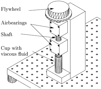 Lab 2: Rotational 1st-order Inertia/Damper System | Modeling Dynamics The pictures related to be able to pwm first order inertia in the following paragraphs, hopefully they will can be useful and will increase your knowledge. Appreciate you for making the effort to be able to visit our website and even read our articles. Cya ~.
 First-order parameter slope according to PWM for each camera First-order parameter slope according to PWM for each camera
 First-order parameter slope according to PWM for each camera First-order parameter slope according to PWM for each camera
 Generation of the PWM signal for the digital filter of the low-pass and Generation of the PWM signal for the digital filter of the low-pass and
 Figure 1 from New optimal settings of PI and PID controllers for the Figure 1 from New optimal settings of PI and PID controllers for the
 Comparison of PSR for the proposed power stage with (a) first-order PWM Comparison of PSR for the proposed power stage with (a) first-order PWM
 Response of digital displacement machine and first order plant for a Response of digital displacement machine and first order plant for a
 Figure 8 from New optimal settings of PI and PID controllers for the Figure 8 from New optimal settings of PI and PID controllers for the
 Response of digital displacement machine and first order plant for a Response of digital displacement machine and first order plant for a
 The first-order inertia response curve of PZT mathematical model The first-order inertia response curve of PZT mathematical model
 Comparison between first and second order RC filter for PWM to analogue Comparison between first and second order RC filter for PWM to analogue
 Inertia emulation control techniques (a) First-order filter-based Inertia emulation control techniques (a) First-order filter-based
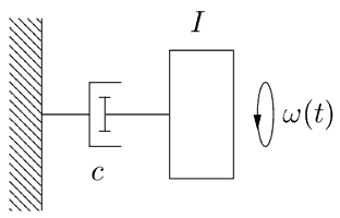 Lab 2: Rotational 1st-order Inertia/Damper System | Modeling Dynamics Lab 2: Rotational 1st-order Inertia/Damper System | Modeling Dynamics
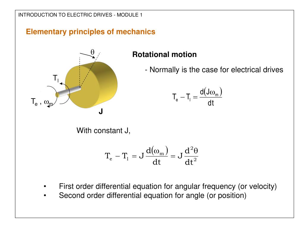 PPT - ELECTRIC DRIVES PowerPoint Presentation, free download - ID:351864 PPT - ELECTRIC DRIVES PowerPoint Presentation, free download - ID:351864
 (PDF) PI Analog Control with Filtering PI Control - PWM w/ Saturation (PDF) PI Analog Control with Filtering PI Control - PWM w/ Saturation
 Comparative Analysis of Controller Tuning Methods for First-Order Comparative Analysis of Controller Tuning Methods for First-Order

 The first-order inertia response curve of PZT mathematical model The first-order inertia response curve of PZT mathematical model
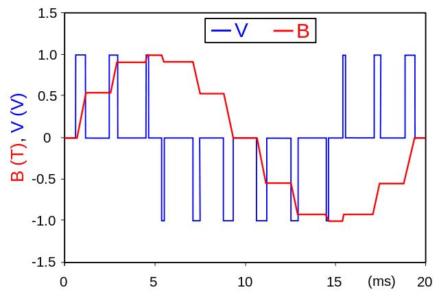 PWM: Pulse Width Modulation: What is it and how does it work? PWM: Pulse Width Modulation: What is it and how does it work?
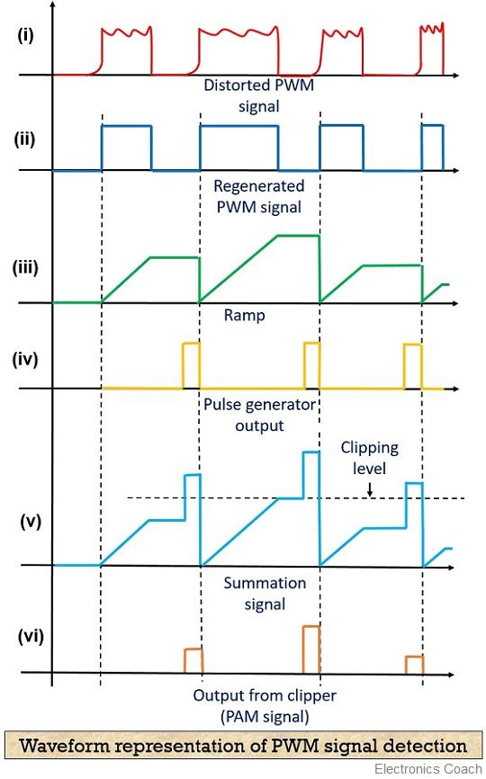 What is Pulse Width Modulation (PWM)? Definition, Basics, Generation What is Pulse Width Modulation (PWM)? Definition, Basics, Generation
 Figure 1 from New optimal settings of PI and PID controllers for the Figure 1 from New optimal settings of PI and PID controllers for the
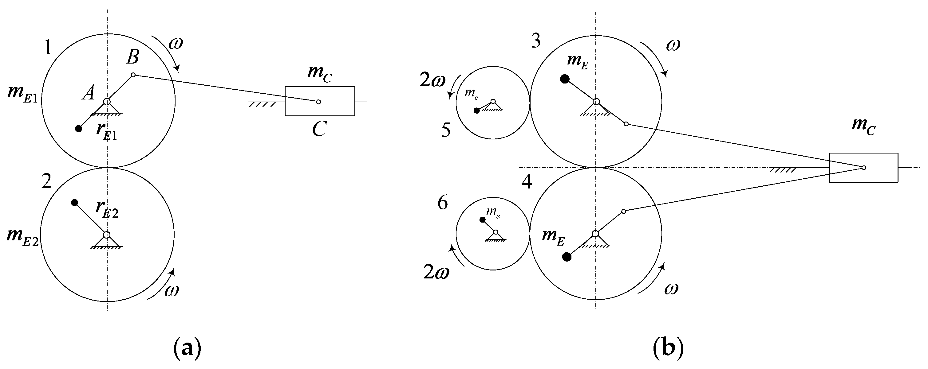 Machines | Free Full-Text | Equilibrium Analysis and Simulation Machines | Free Full-Text | Equilibrium Analysis and Simulation
 2: Step response for big inertia and estimated models First order 2: Step response for big inertia and estimated models First order
 (PDF) Multibit ΣΔ PWM digital controller IC for DC-DC converters (PDF) Multibit ΣΔ PWM digital controller IC for DC-DC converters
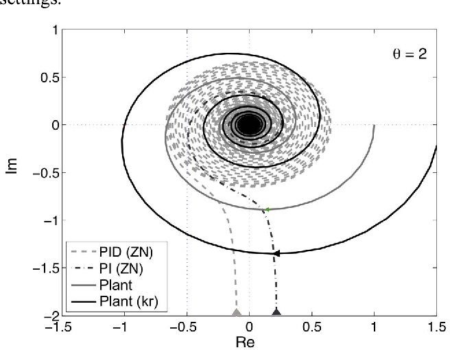 Figure 1 from New optimal settings of PI and PID controllers for the Figure 1 from New optimal settings of PI and PID controllers for the

